Masking and blending decide how much of a processing module’s effect actually reaches the image, and where – from applying it uniformly across the whole frame down to targeting a handful of pixels.
Each module takes its input from the preceding module in the pixelpipe, performs its operation, and hands the output to the next module. Blending is the optional step in between: a module’s output data can be reprocessed (combined) with its input data using algorithms called blending operators, or blend modes, before being handed onward.
Each blend mode is further controlled by the opacity parameter (having a value between 0% and 100%) which defines how much the input or output images contribute to the final result. Typically an opacity of 0% outputs an image which is identical to the input image (the module has no effect) whereas an opacity of 100% delivers the maximum effect of the module.
This opacity can be the same for every pixel (using the global Opacity slider), in which case blending acts uniformly over the entire image. Alternatively the opacity values can vary depending on the properties or location of each pixel. This local modification of opacity is called a mask, and it is what gives you fine control over which parts of an image a module affects, and to what extent.
These controls are shown in the Masking & Blending tool in the darkroom left panel: focus a module that supports blending (click its header) and this panel switches to show that module’s blending controls. With no module focused, or a module that doesn’t support blending, the panel says so instead.
The drawn shapes you create there are the same objects managed by the shape manager, a separate floating window, and can be reused across modules.
Enabling blending and masking
Blending is switched on per module by the Enable checkbox at the top of the panel. While it is unchecked, blending and masking are off entirely: the module’s output goes straight to the next module in the pixelpipe with no additional reprocessing, and the rest of the panel stays grayed out.
Check it and blending applies uniformly over the whole image, which is the state you get before any mask is involved: input and output are combined with the chosen blend mode, in an amount set by the global Opacity slider. The defaults – a blend mode of “Normal” at 100% opacity – reproduce the module’s plain effect.
Adding a mask is what makes that opacity vary from pixel to pixel instead of being the same everywhere. Each masking method has its own tab, and all three – Raster, Drawn and Parametric – are enabled by default: switching blending on is enough to start using any of them, and they stay uniform until you actually draw a shape, move a parametric slider or pick a raster source. Use as many at once as you need (see combining masks below); each masking tab has its own Disable checkbox to turn that method off when you want it out of the way.
- Drawn mask
- The opacity is based on pixel location, as defined by one or more shapes drawn on the image. Until you draw a shape, every pixel keeps the same opacity, as set by the global Opacity slider.
- Parametric mask
- The opacity is based on the properties of individual pixels, computed per-pixel from their values in the color channels you choose.
- Raster mask
- The opacity is based on a mask that was generated by another module earlier in the pixelpipe.
A fourth tab, Contours, carries no Disable checkbox of its own because it defines no mask: it refines whichever mask the other tabs produce, blurring and feathering it so its edges follow the details of the image. See mask contours.
Blending options
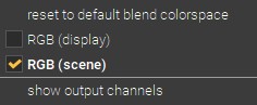
The button  at the right end of the tab row opens a menu of options for the parametric mask; it stays grayed out on modules that don’t support one. Use it to pick the color space the parametric mask is computed in, and to show the output-channel sliders (a parametric mask is normally built from the input channels coming into the module):
| Reset to default blend colorspace Goes back to the module’s own default color space. |
| Lab Uses the Lab color space. Offered only for modules that natively work in Lab, so that Lab blending is not applied where it doesn’t belong. |
| RGB (display) Uses the display-referred RGB/HSL color space. |
| RGB (scene) Uses the scene-referred RGB/JzCzhz color space. |
| Show output channels Shows the output channel sliders, so the parametric mask can also be defined in terms of the module’s output. Once they are shown, this entry becomes Reset and hide output channels. |
Note
Not every blend mode or blending option is available for every module – the choices on offer depend on the color space the module works in.
Combining masks
The three masking methods are independent toggles that can be combined. A raster mask serves as the base when one is active, and the drawn and parametric masks refine it from there.
How those masks are folded together is set by Combine masks, whose two modes are mirror images of each other:
| Exclusive (default) Multiplies the masks together before applying the global Opacity slider. A pixel excluded by any one mask (opacity 0) stays excluded, so each mask you add can only ever restrict the affected area. |
| Inclusive Inverts each mask, multiplies, then inverts the result. A pixel fully included by any one mask (opacity 1.0) stays included, so each mask you add can only ever extend the affected area. |
Deciding which of the two you want before you start is the easiest way to keep a complex mask predictable — see combining drawn & parametric masks for the polarity settings that go with each.
Previewing the mask
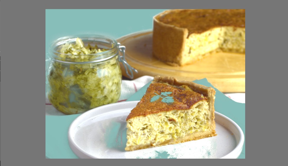
A mask is easier to judge when you can see it. The mask icon, both in the module’s header and in the blending panel, replaces the center view with a preview of the mask the module is currently using.
Read it as a cut-out rather than as a highlight:
- Where the image shows through, the mask is at full opacity and the module’s effect is applied.
- Where the checkerboard shows, the mask is at zero and the module is not applied — that part of the picture is masked out, so it is hidden from view.
- In between, the image and the checkerboard mix in proportion, so a soft edge fades from one to the other.
The checkerboard pattern is deliberate: it makes a partly transparent mask legible in a way a flat color cannot, since you can tell a half-hidden area from a fully hidden one at a glance.
Mask preview settings
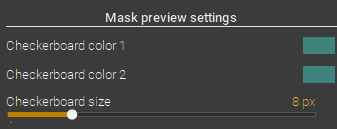
The look of the preview is set in the Picture display options popover, opened by the Display button  in the toolbox at the bottom of the darkroom left panel. Its Mask preview settings section holds:
| Checkerboard color 1 and Checkerboard color 2 The two alternating squares. Picking colors that clash with the image you are working on is what makes the masked areas obvious — a neutral pair disappears against a busy picture. |
| Checkerboard size The size of a square, from 2 to 32 px (default 8). Larger squares are easier to see; smaller ones obscure less of a finely detailed mask edge. |
| Show a greyscaled mask image Converts the visible part of the image to grayscale during the preview, so the only colors on screen are the checkerboard’s. Useful when the picture’s own colors make the mask boundary hard to follow. |
The same popover carries Fast drawn mask rasterization, which trades a little accuracy in how brush and polygon masks are drawn on screen for speed when zoomed out. Exports, thumbnails and snapshots stay pixel-accurate either way.